Engineering |
||||||||||||||||||||||
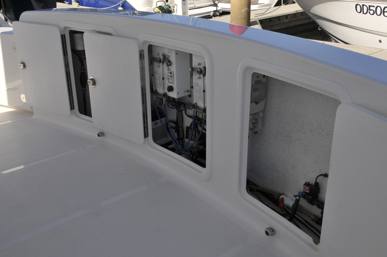
The systems engineering of the vessel has been geared for the coastal cruising role. The installation arrangement is designed for serviceability down the road rather than just targeting ease of manufacture. For example all of the equipment associated with the engines (including fuel filters, starting battery, battery switching, engine controls, hydraulics and fresh water flushing) is located behind locker doors in the back beam. This location means that the equipment has easy service access and is mounted high above possible flooding. The end result is higher reliability, a reduced total cost of ownership for the owner and less warranty effort for the builder.
|
|
|||||||||||||||||||||
Engine Systems |
||||||||||||||||||||||
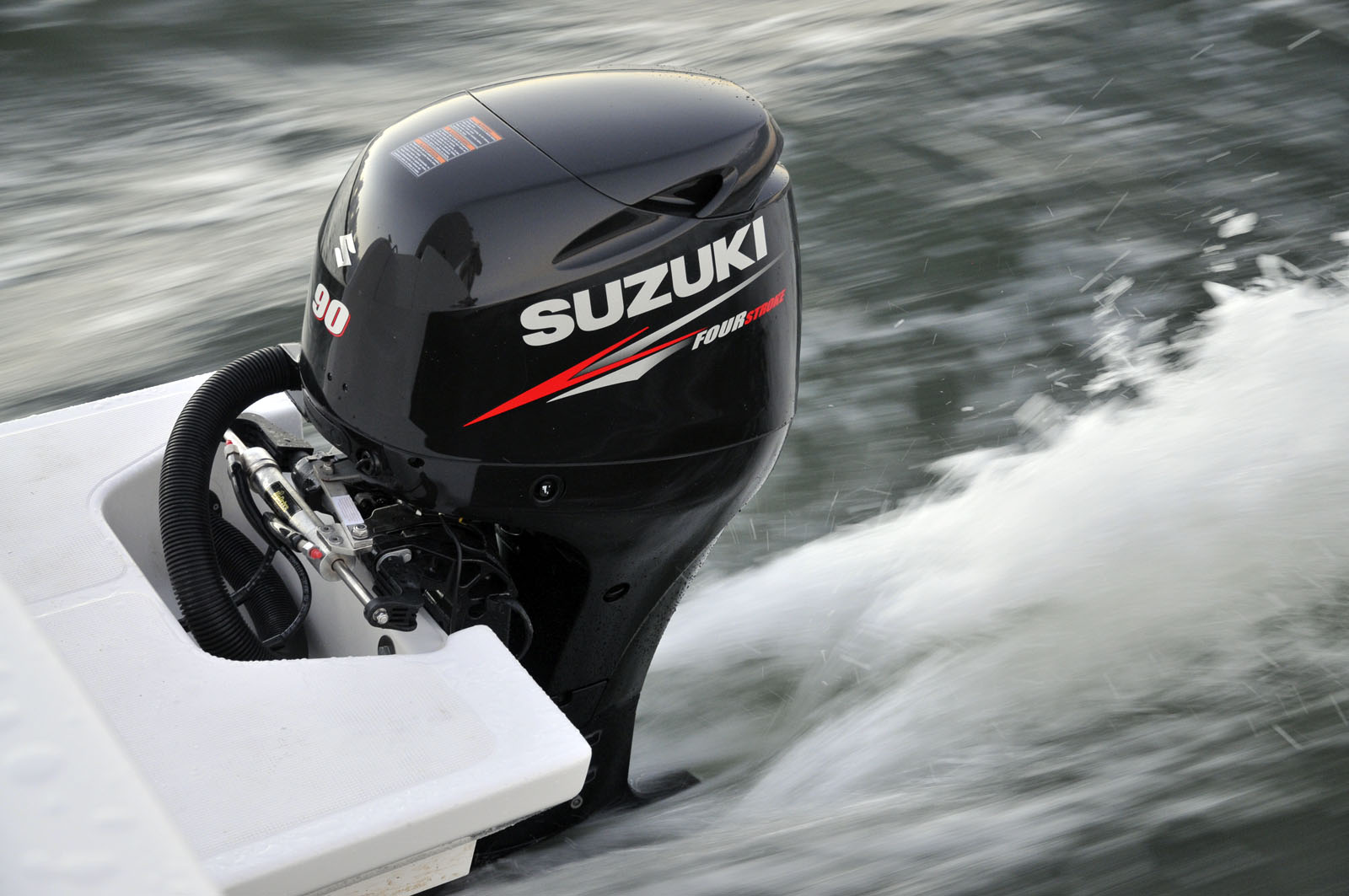
The vessel is fitted with two Suzuki DF90A 4-stroke engines. At anchor or dock the raised outboard legs are completely clear of the water which means that antifouling is not required.
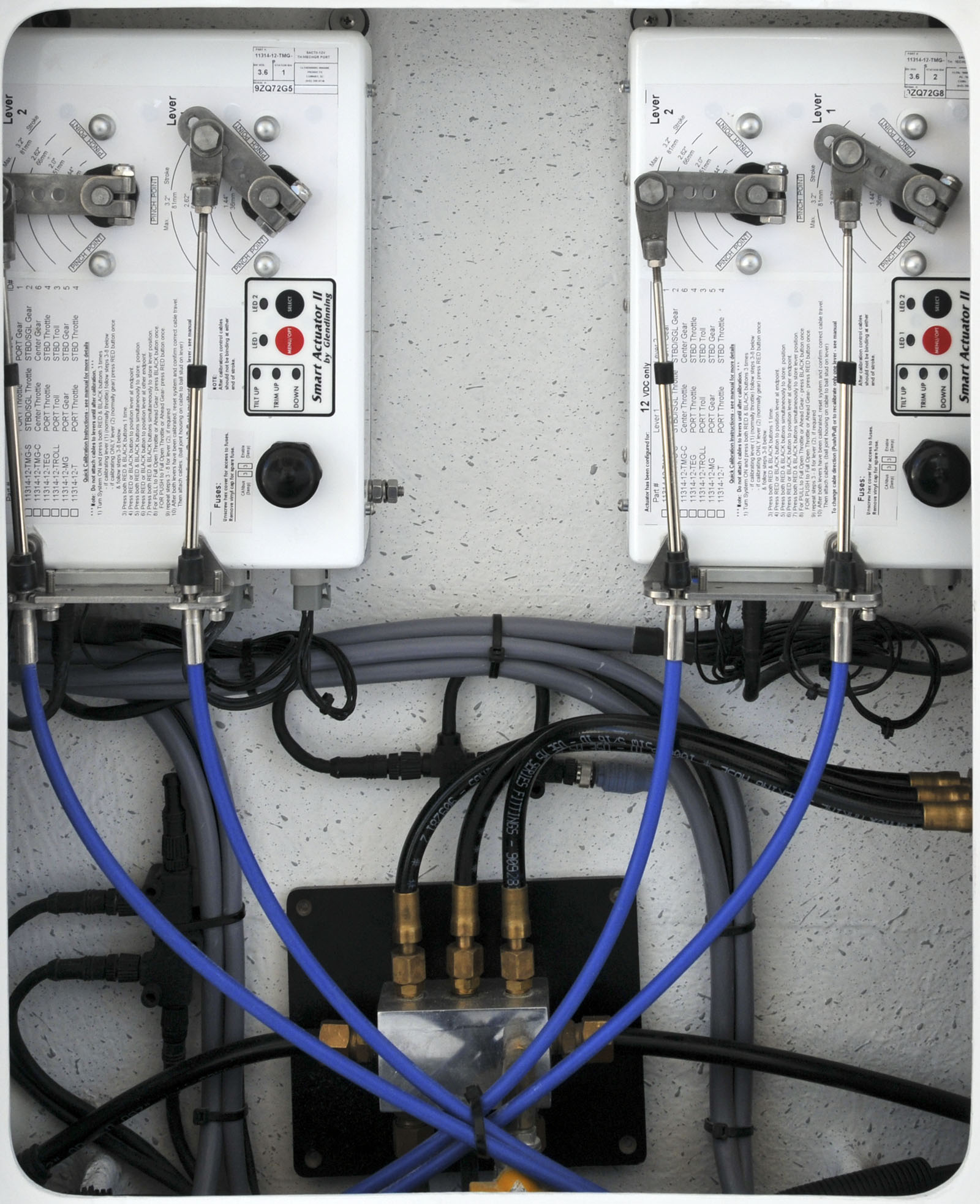
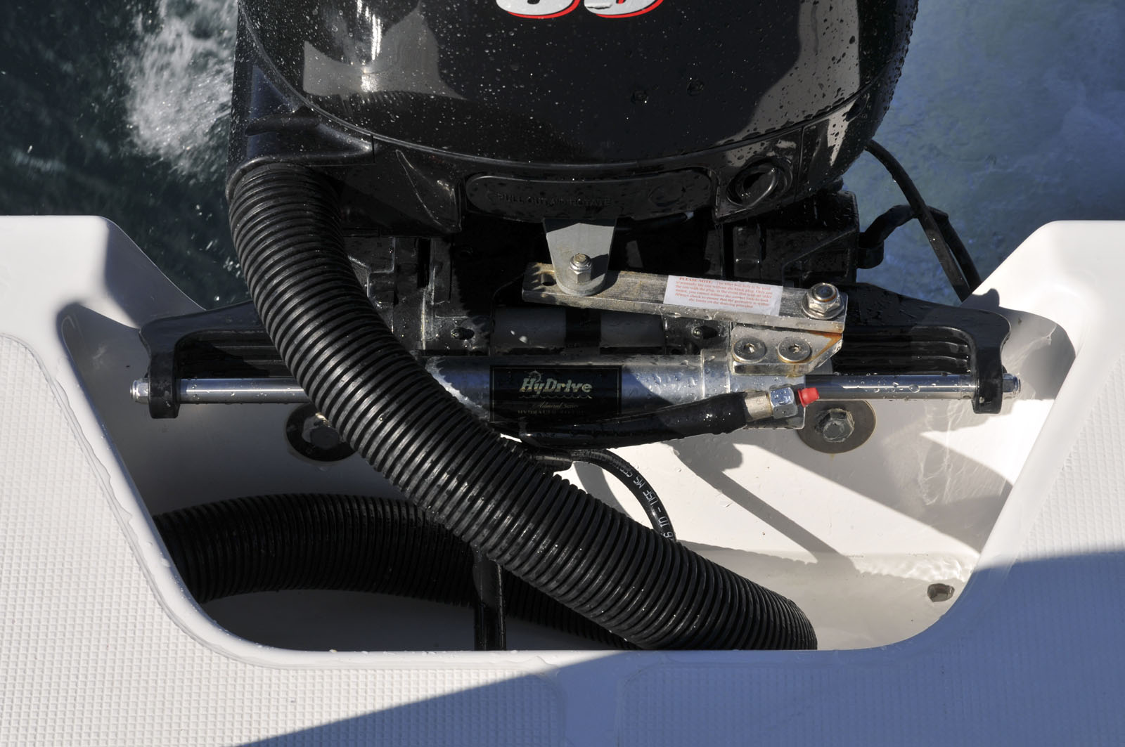
Extensive in water testing has resulted in the selection of Rubex 13.75" x 14" 3 blade stainless steel propellers. A NMEA-2000 digital communications link allows the engine electronics to share data with third party instrument manufacturers. Engine data including RPM, fuel consumption, trim angle, engine temperature and cooling water pressure is displayed on the standard Raymarine navigation display. Inboard diesel engines are available as a purchase option. The diesel engines are located in the current aft lazarettos. The installation will use shaft drives with a tunnel hull to reduce draft. The propellers are fully protected by mini keels. The diesel option will increase vessel draft from 600 mm to 700 mm. Fuel SystemEach engine has an independent fuel system. A nominal 300 litre capacity baffled fuel tank is located in each hull just aft of the companion way bulkhead. The tanks are fully serviceable in that they can be removed if the need ever arises - although it is not expected. Each is fitted with a fuel level sensor that provides level data to the NMEA-2000 instrument network. The fuel lines lead to primary fuel filters which are located above deck level on either side of the back beam for ease of access. A priming bulb is fitted to the inlet side of each filter. Engine ControlsThe total run length from the helm to the engines is over 12 metres. As an alternative to a mechanical engine control system, Glendinning electronic throttle and gear shift controls are standard fitting. The "fly by wire" system has a compact control head at the helm that communicates over a CAN bus to the actuators that are mounted in the back beam of the vessel. This means that the length of throttle and gearbox control cables is kept to a minimum which in turn decreases friction and improves sensitivity. The smart control system has many programmable features. For example a delay is programmed to ensure that engine RPM has returned to an idle before allowing a shift from forward to reverse. Another feature is automatic engine RPM synchronisation. By pressing a button at the control head, the throttle position of both engines is controlled by the port throttle lever. Installation of the system has been simplified and reliability of connections improved by using a special engine interface board that handles the interconnection of engine loom, helm key start controls and the Glendinning actuators. LED indicators provide an easy status reading of electrical power and ignition return. Engine FlushingAn active maintenance feature is the provision of engine flushing solenoids. A momentary switch located in the starboard side of the aft beam activates a timer that succesively flushes the port and starboard engines with water from the vessel pressurised fresh water system. Trim and TiltAdditional trim and tilt controls have been added at the aft beam to allow fine tuning of trim while under way and to conveniently tilt the engines up when at anchor or at the dock. Hydraulic SteeringA Hydrive steering ram is fitted to each engine and a hydraulic tie bar is connected between the engines. An autopilot pump is fitted in the aft bulkhead area. The aft pump location eliminates autopilot pump noise in the vessel interior. A hydraulic steering manifold consolodates connections into a compact area and provides a balancing valve for the tie bar. A small keel section is provided under each hull to maximize steering responsiveness. |
||||||||||||||||||||||
Helm - Electronics |
||||||||||||||||||||||
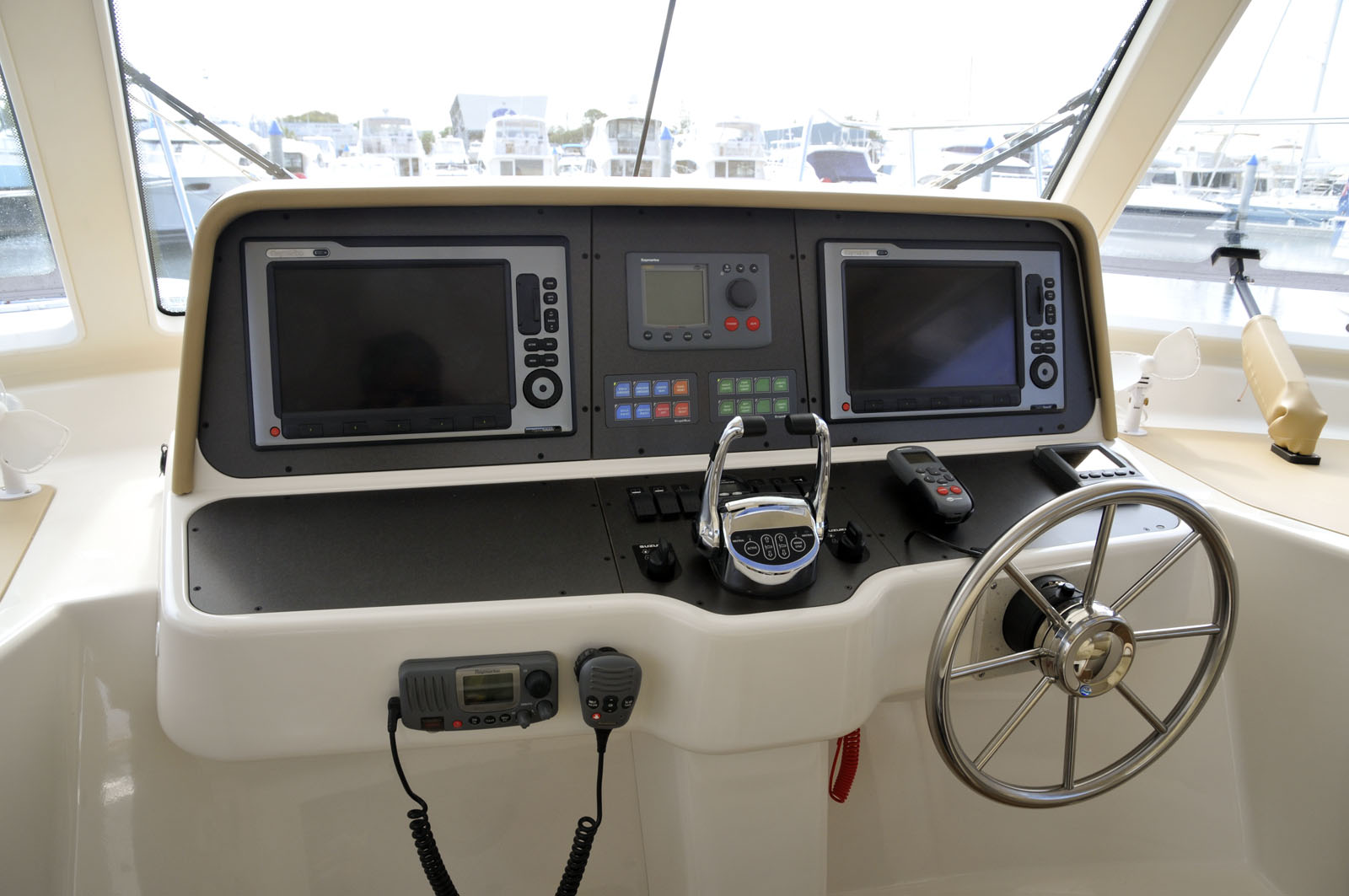
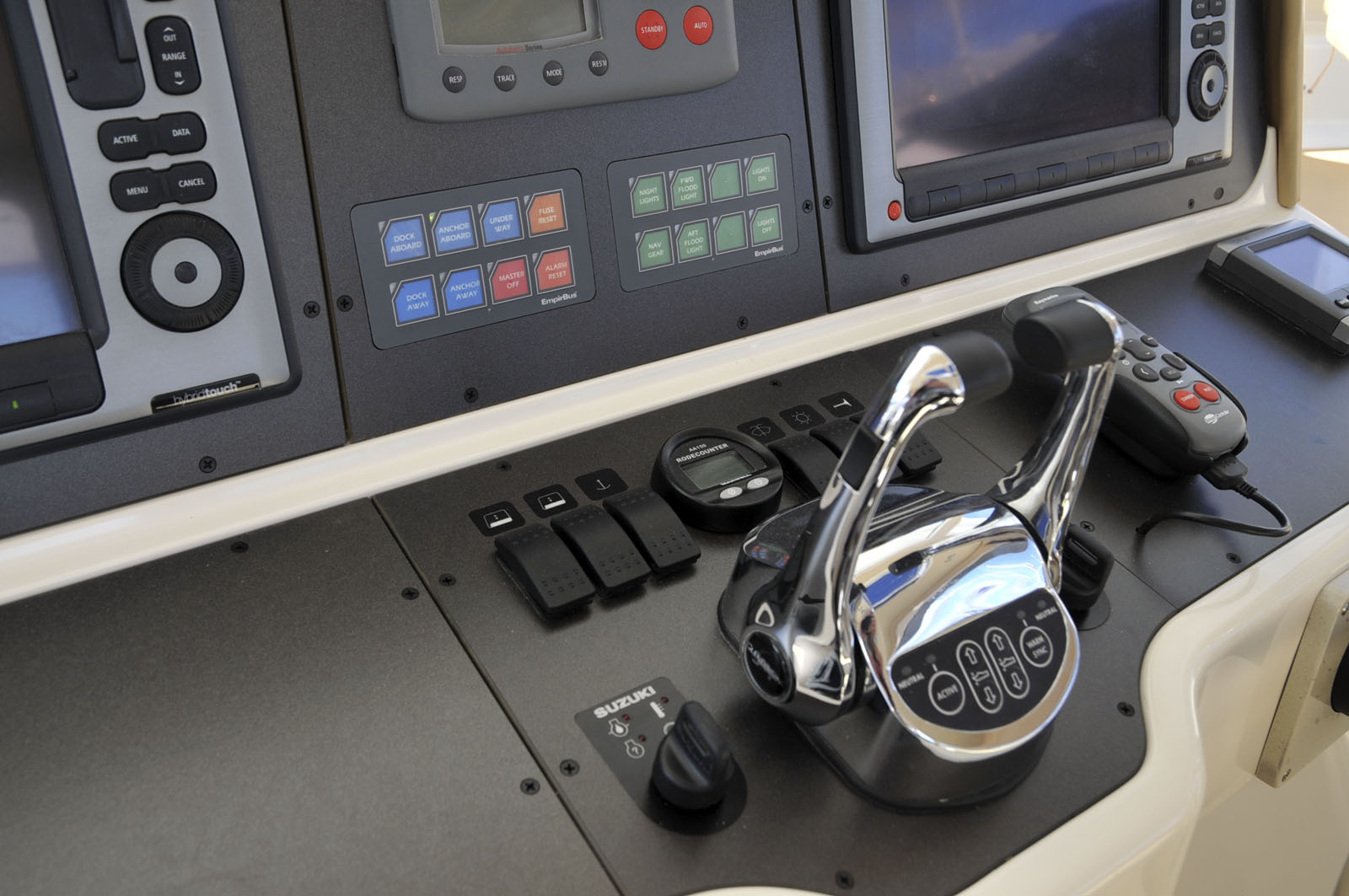
A centrally located helm console is flanked by two work areas that easily accomodate charts or a laptop computer. All helm components are mounted on removeable compact laminate fascias that are fully replaceable to accomodate helm instrument upgrades in the future. The helm cover is well ventilated to allow appropriate cooling of helm instruments and it is removeable to provide rear access. 12 volt DC outlets are located on either side and a 240 volt outlet is located to port. A stainless steel wheel is mounted on the hydraulic helm pump on the starboard side. Drive the boat functions including morse control, dash switches and autopilot are arranged in the centre of the helm unit to be accessible from either helm seat location. The electronic Glendinning morse control head features fingertip control and automatic engine RPM synchronisation. Either side of the morse control are the engine start key switches and warning lights. Rocker switches are used for control of devices while driving the boat. These include port and starboard window operation, anchor up/down, windscreen washer/wiper, overhead lights and air horn. An electronic rode counter assists with anchor deployment and retrieval. Vessel mode control push button switches organise the vessel electrical system according to the mode of operation. Modes include Dock Away, Dock Aboard, Underway, Anchor Aboard and Anchor Away. The vessel is fully equipped with a Raymarine Coastal Cruising Package suitable to support coastal cruising navigation. A 12" multifunction colour display with integral GPS is equipped with Australia wide charts. The display also interfaces to a saloon roof mounted radome, the autopilot computer and a fish finder transducer to provide an integrated navigation solution. A DSC equipped VHF radio and a class B AIS system round off the safety package. Ample space is provided either side of the helm to accommodate owner provided paper charts. A single tower accomodates the radar dome, VHF radio antenna, TV antenna, air horn trumpets and all round white navigation light. There is room for the optional weather station transducer.
|
||||||||||||||||||||||
Electrical System |
||||||||||||||||||||||
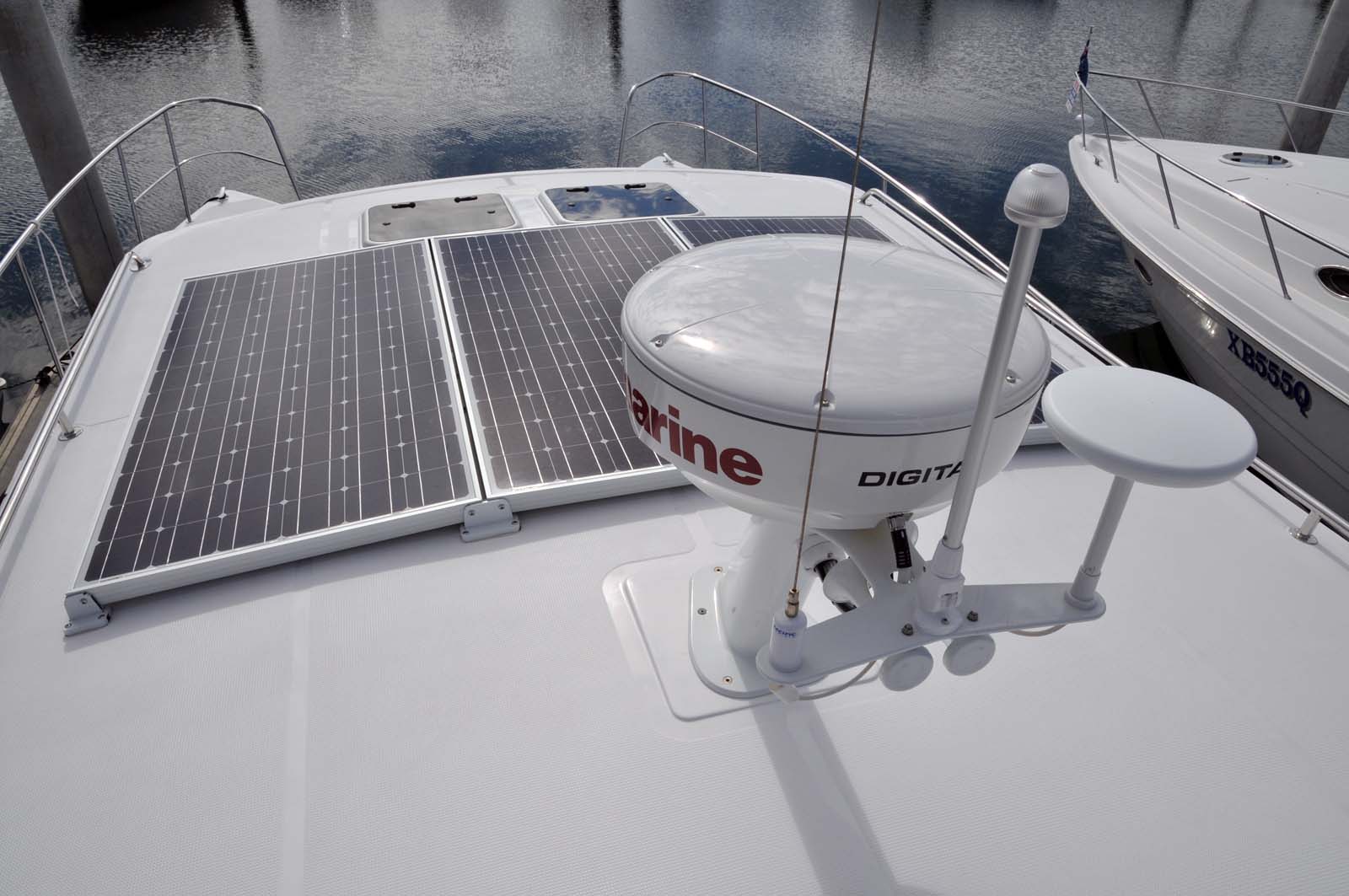
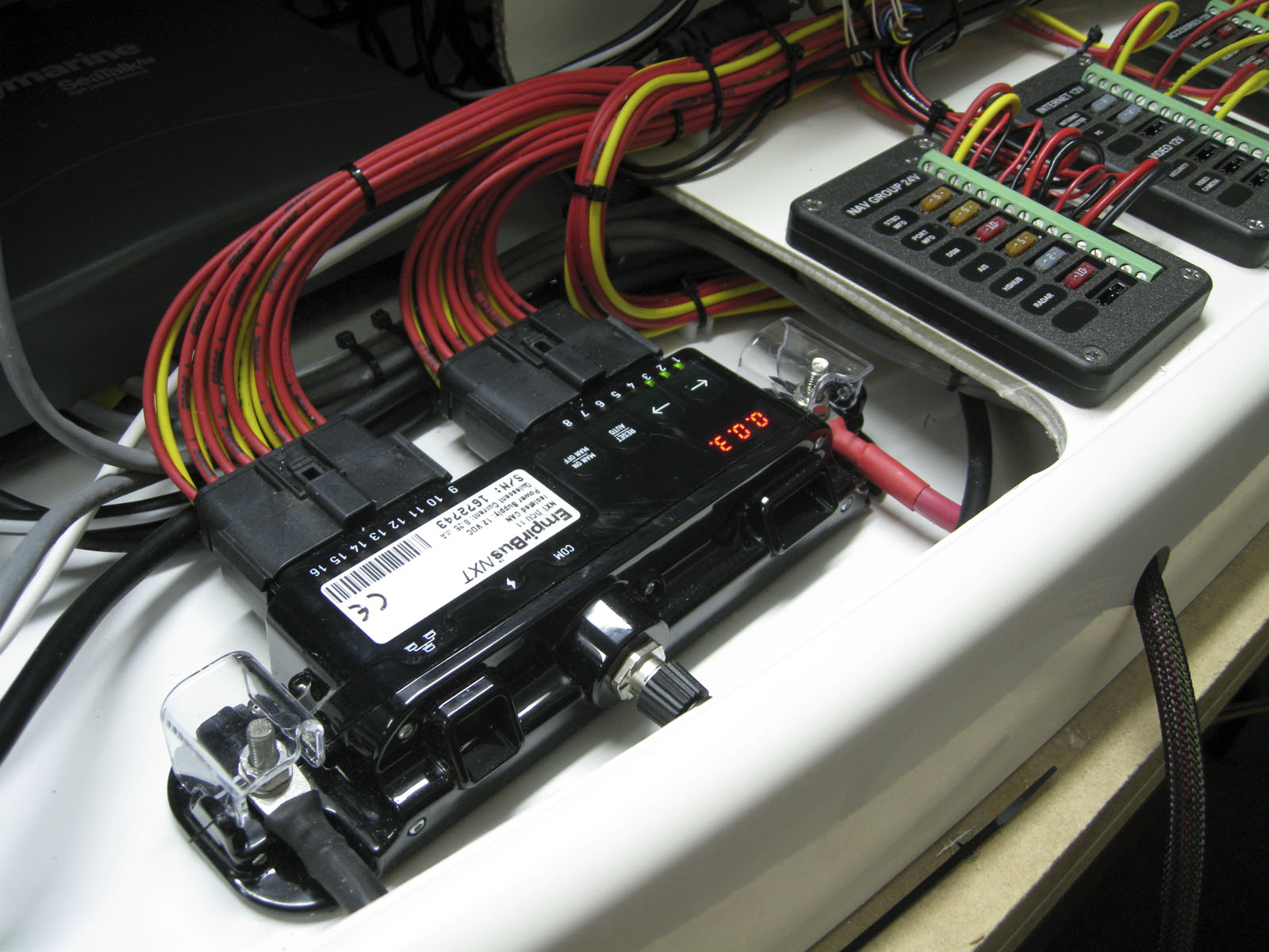
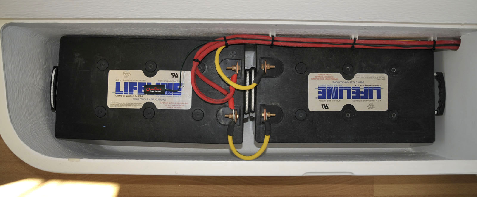
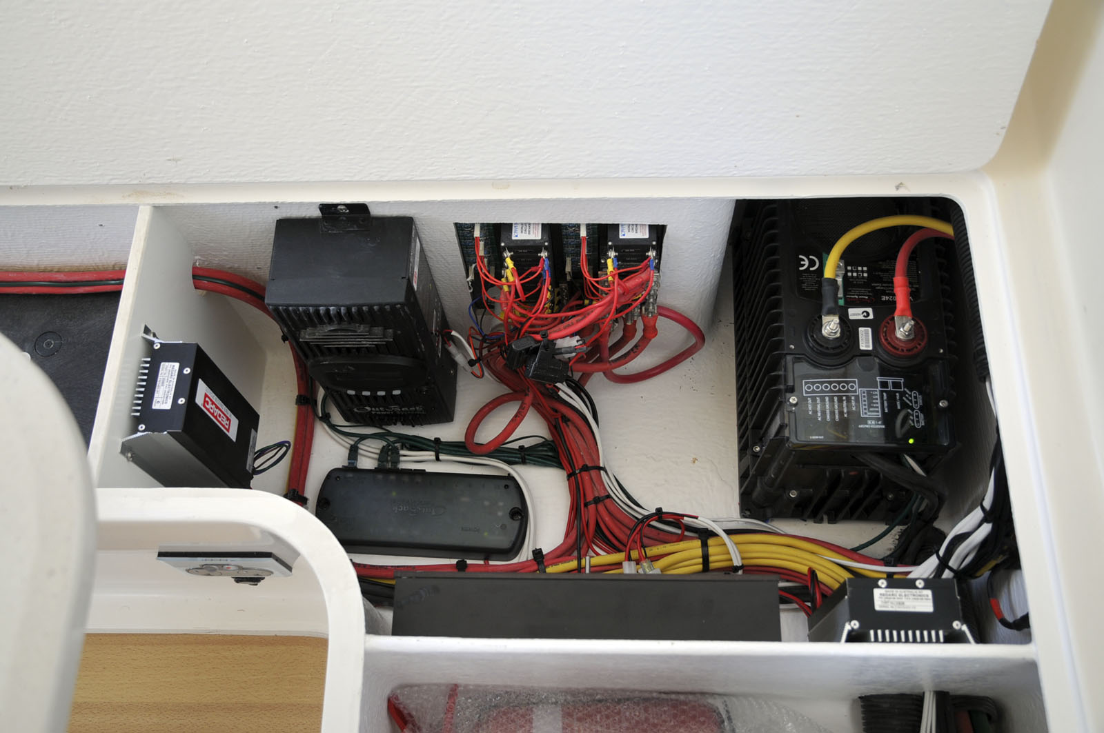
The vessel electrical system is designed to provide vessel power while away from the dock without the need for a generator. Power is provided by 3 solar panels totaling over 500 watts mounted on the roof with an additional 500 watts available as an option for more temporate climates. The Suzuki engines provide power while under way and an optional 1000 watt petrol generator may be used as a backup on occasion when the solar energy is not sufficient. Vessel electrical power is stored in a 24-volt house battery bank comprising two 255 amp hour AGM batteries. A 12-volt starting battery looks after engine cranking with emergency backup provided by the house battery bank. The battery management system automatically maintains cross charging of the batteries. Solar charging is regulated by a maximum power point tracking regulator that operates the solar panels at their most efficient power output according to sun exposure and battery state of charge. This means that the solar charging system efficiency is particularly enhanced in overcast conditions. A 3000 watt inverter converts battery power to 240 volt AC power for use by vessel appliances. Power outlets are available at the galley bench, helm and saloon table. The electrical switch panels are located in the galley. The electrical system is centrally located under the starboard side settee seat. The main DC distribution board has battery isolation switches and fused connections for each heavy DC supply. An engine power board mounted aft has separate power switches to isolate engine power for maintenance. Vessel power is managed by an Empirbus distributed power and control system. The system eliminates the need for conventional switchboards and provides simple yet powerful system operation incorporating vessel modes. |
||||||||||||||||||||||
 Major electrical components under settee |
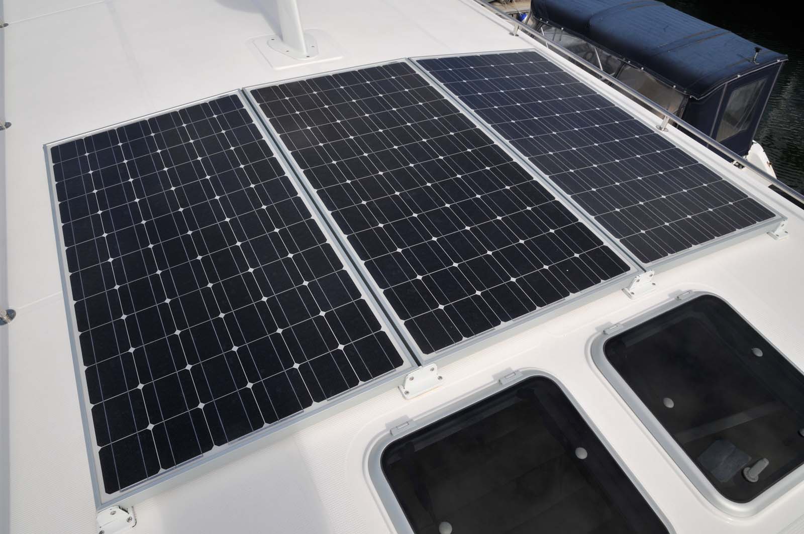 3 x 170 watt Solar Panels |
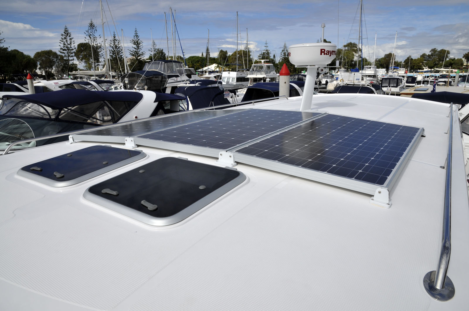 Solar Panels |
||||||||||||||||||||
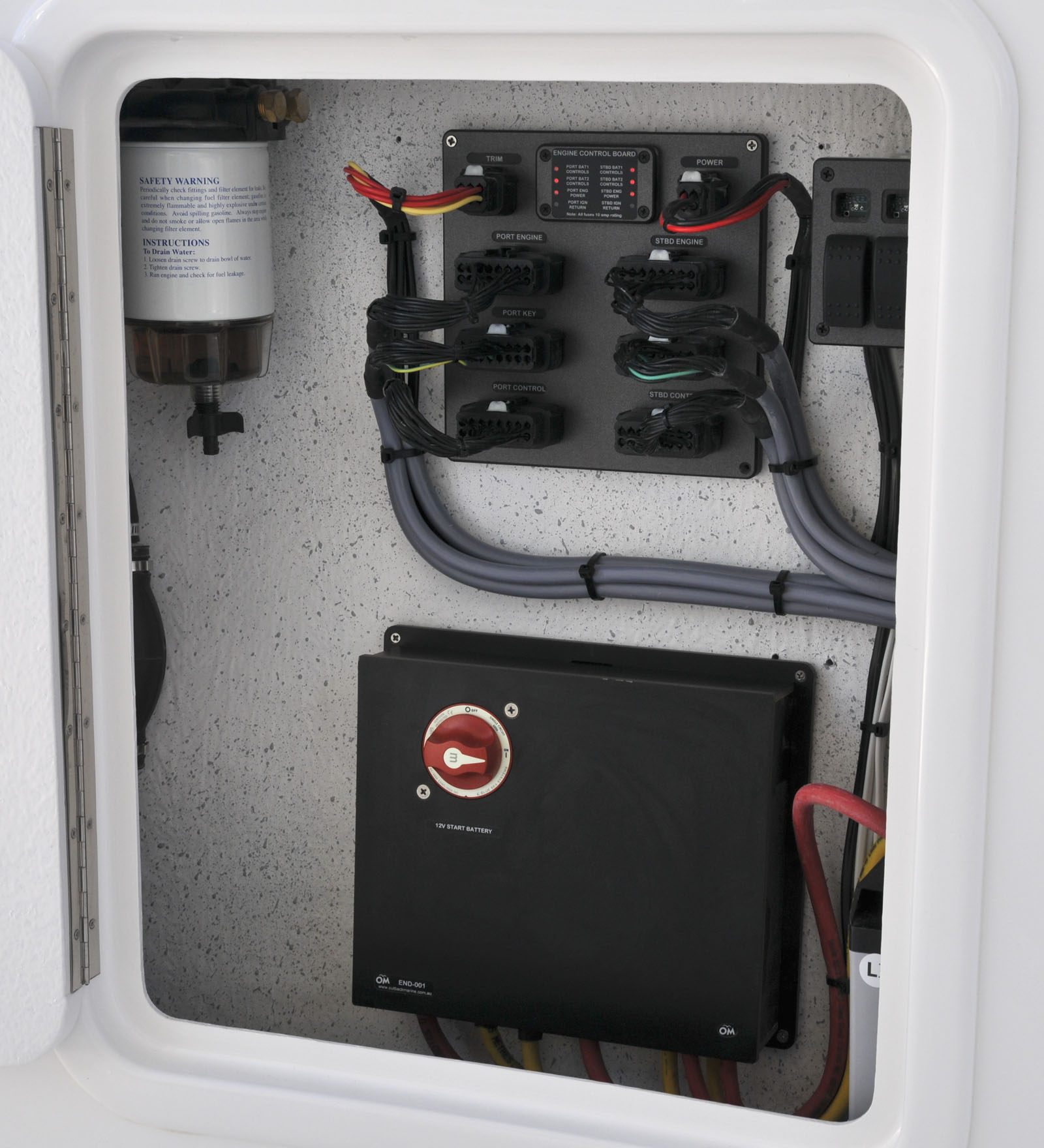
 Engine Battery Power Distribution |
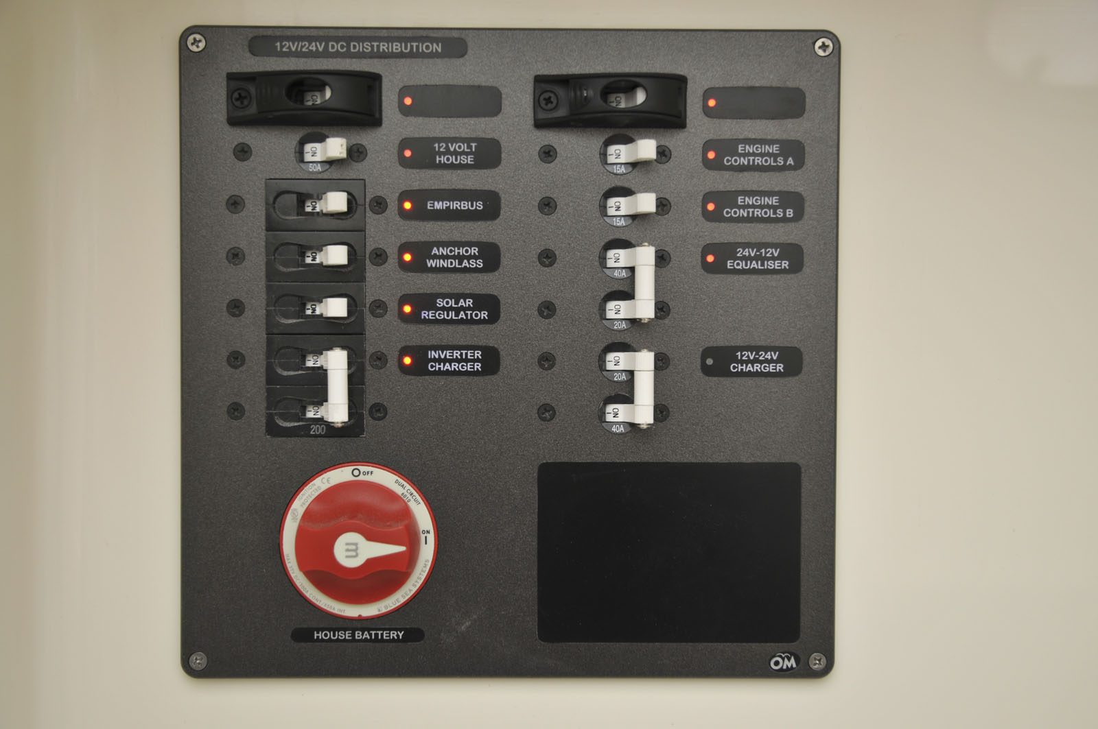 Main DC Panel |
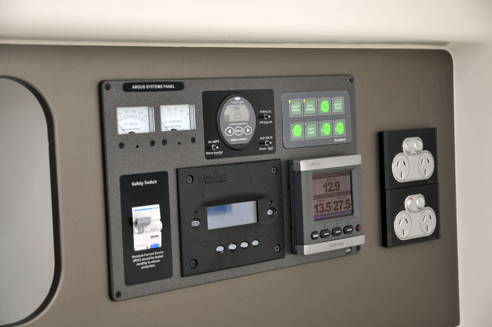 Vessel Systems Panel |
||||||||||||||||||||
Bilge Pumping System |
||||||||||||||||||||||
There are no bilges in a loose sense, the lower parts of the hulls are double skinned meaning that any fracture below the floor levels would limit water ingress to that cavity. The bow areas are constructed using sealed collision bulkheads. There is no engine room space so there is no requirement for "engine room" bilge pumping. However for convenience if a pipe leak occurs somewhere, a portable electric bilge pump with a length of hose is provided. This pump can be deployed anywhere in the vessel. The aft deck lockers have a bilge well at their lowest point for esy water pickup. The image at right shows the well next to the refrigeration system keel cooling pipes and a fuel tank. |
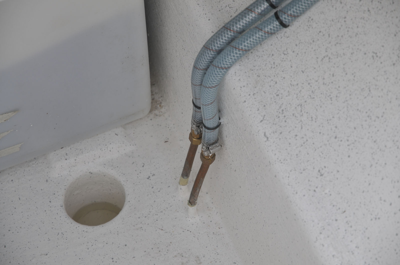 Fuel tank - bilge well - keel cooler |
|||||||||||||||||||||
Refrigeration |
||||||||||||||||||||||
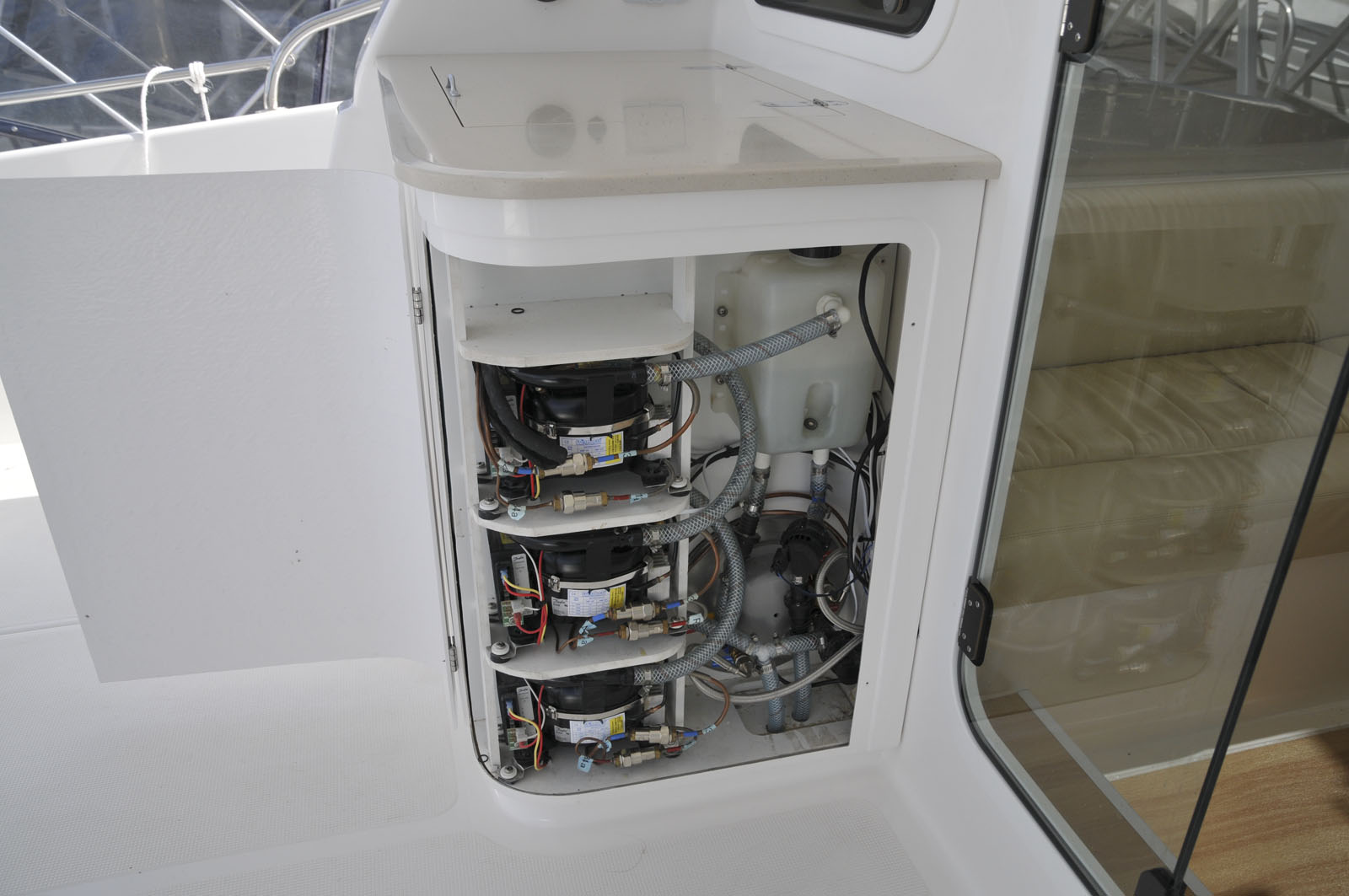
The refrigeration system components are located behind a service door inside the port refrigeration cabinet. Instead of discarding waste condensor heat from the refrigeration system, a heat pump configuration is used to heat the hot water system. The system uses a water cooling circuit for each condenser set. Water is recirculated through a pipe embedded into the lay up of the port hull which exchanges heat from the outside water in conventional configuration. A parallel cooling circuit recirculates water through a heat exchanger on the vessel hot water system. Each refrigerator and the hot water system has a digital thermostat to control temperature. The port side deck refrigerator can be set for either refrigeration or freezer temperatures. It is built using 100 mm of closed cell foam insulation. The starboard side refrigerator is intended for cold drink storage. The galley is fitted with a pull out refrigerated drawer that is used as a galley working refrigerator. All compressors are powered from the 24 volt house battery bank and the vessel solar panel capacity is capable of maintaining all refrigeration on a continuous 24/7 basis provided that sufficient sun light is available. |
||||||||||||||||||||||
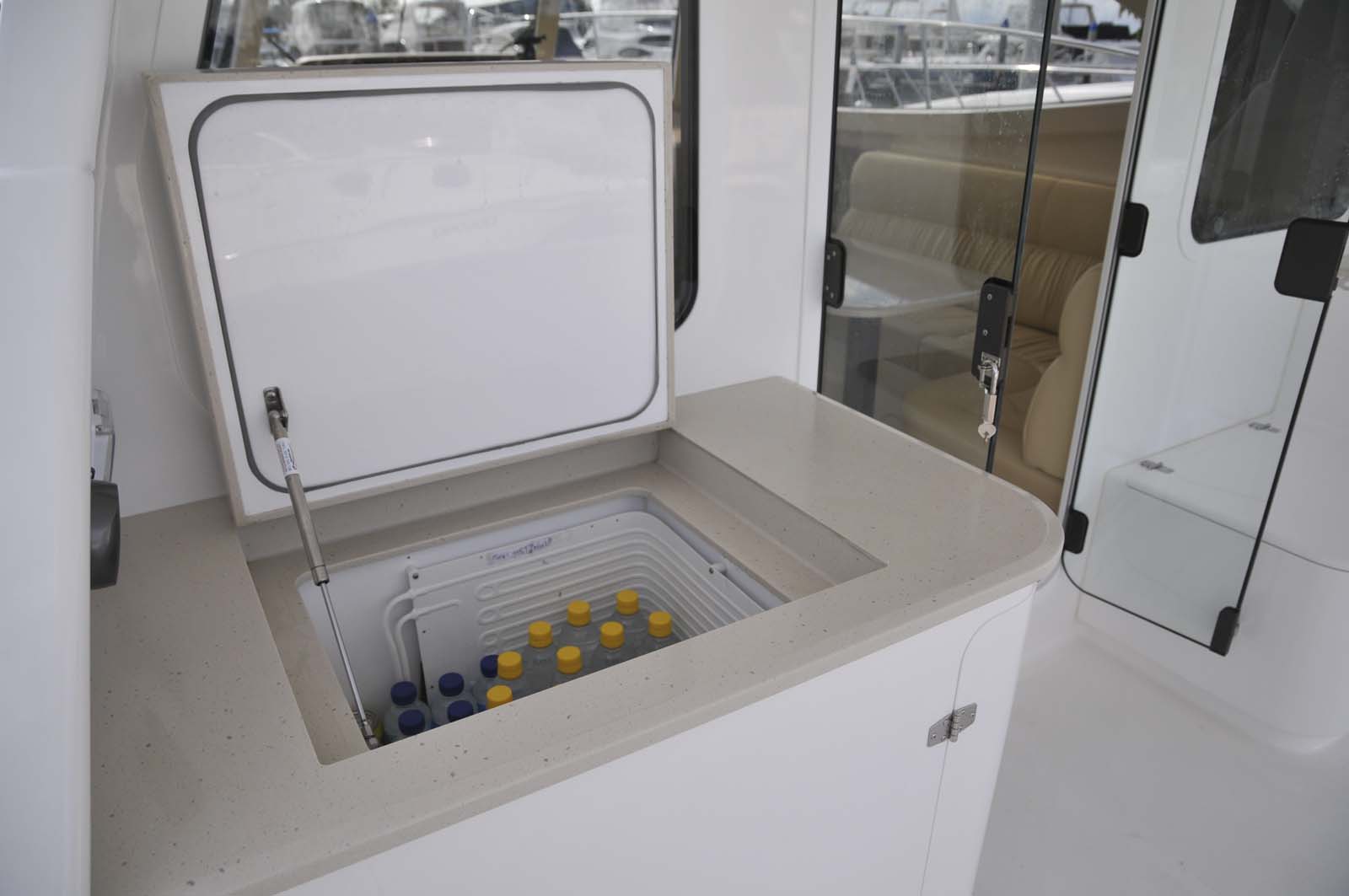 Port Side Fridge / Freezer |
 Stbd Side Drinks Refrigerator |
 Galley Refrigerator |
||||||||||||||||||||
Plumbing System |
||||||||||||||||||||||
Two fresh water tanks of 200 litre capacity each are located under the floor of the forward cabins. The tanks are fitted with tank level senders that connect to level gauges at the electrical house panel. For use in remote cruising applications, provision is made for installation of a 24 volt powered desalination system in the starboard hull aft of the fuel tank. A reverse cycle heat pump system utilises waste heat from the refrigeration system to heat the vessel hot water. A target hot water system temperature of around 38 degrees celcius is maintainable. An electrical heating circuit can be used from shore power or to supplement the heat pump system with an on board generator if required. The hot water system is located under the fridge/reezer cabinet on the aft deck. The toilet system is fitted with a holding tank located behind the aft toilet bulkhead. Either fresh or salt water can be selected for toilet flushing. The electric toilet pumps waste to the tank which is fitted in an above waterline configuration to allow gravity discharge through a below waterline hull fitting (if allowed by local law). A deck fitting is installed for suction pump out. The tank breaths through a pipe connected to a skin fitting. Full service is available to the holding tank by a removable panel on the aft head bulkhead. The tank is fitted with a level sender. The shower pan has an integrated sump that is covered with a grill. The sump is fitted with a pipe that connects to a diaphragm pump that pumps the grey water waste overboard through a skin fitting located just above the waterline on the inboard side of the starboard hull. The galley sink is self draining to a skin fitting located just above waterline on the inboard side of the port hull. All pumps are located at the aft bulkhead of the head area behind a removable panel. Any leak that may occur is limbered directly into the shower wet area. |
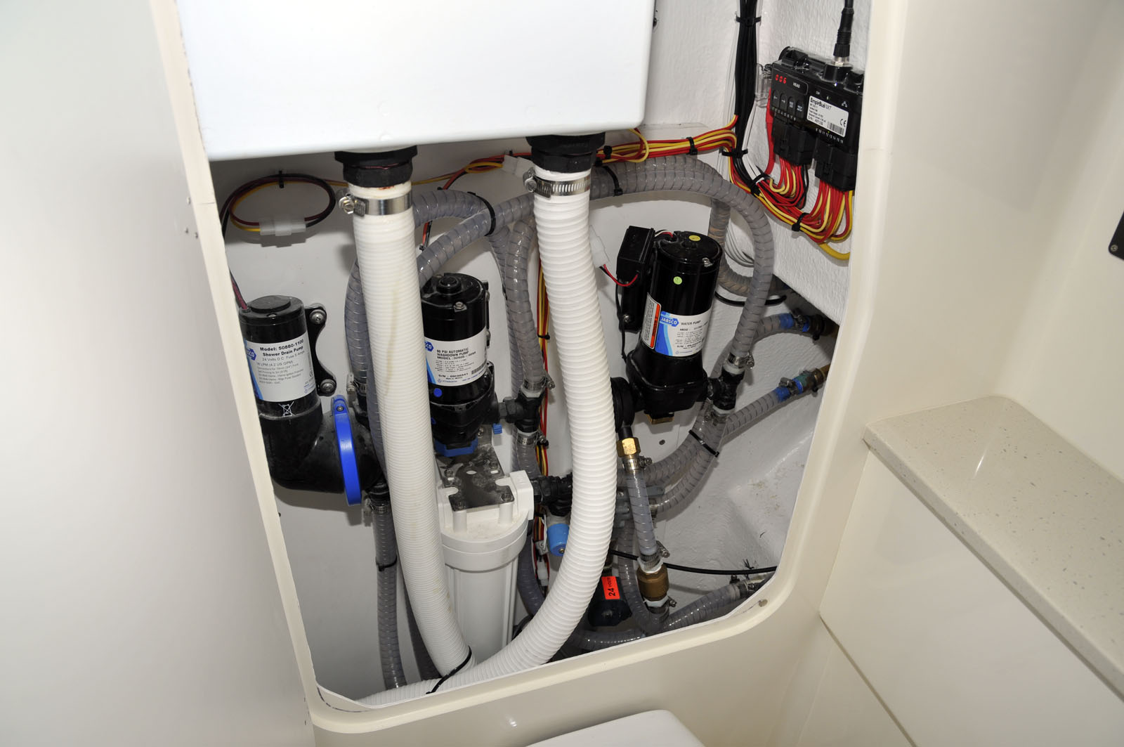 Pumps on Plumbing Bulkhead |
|||||||||||||||||||||